25+ wireless power transmission block diagram
Power flow in WPT system The block diagram of the Power flow in WPT system becomes as shown in Figure 6. PoE-powered devices are usually VoIP Internet phones wireless access points web cameras and any other device that can use 13 255 or 51 Watts of DC power over Cat5.
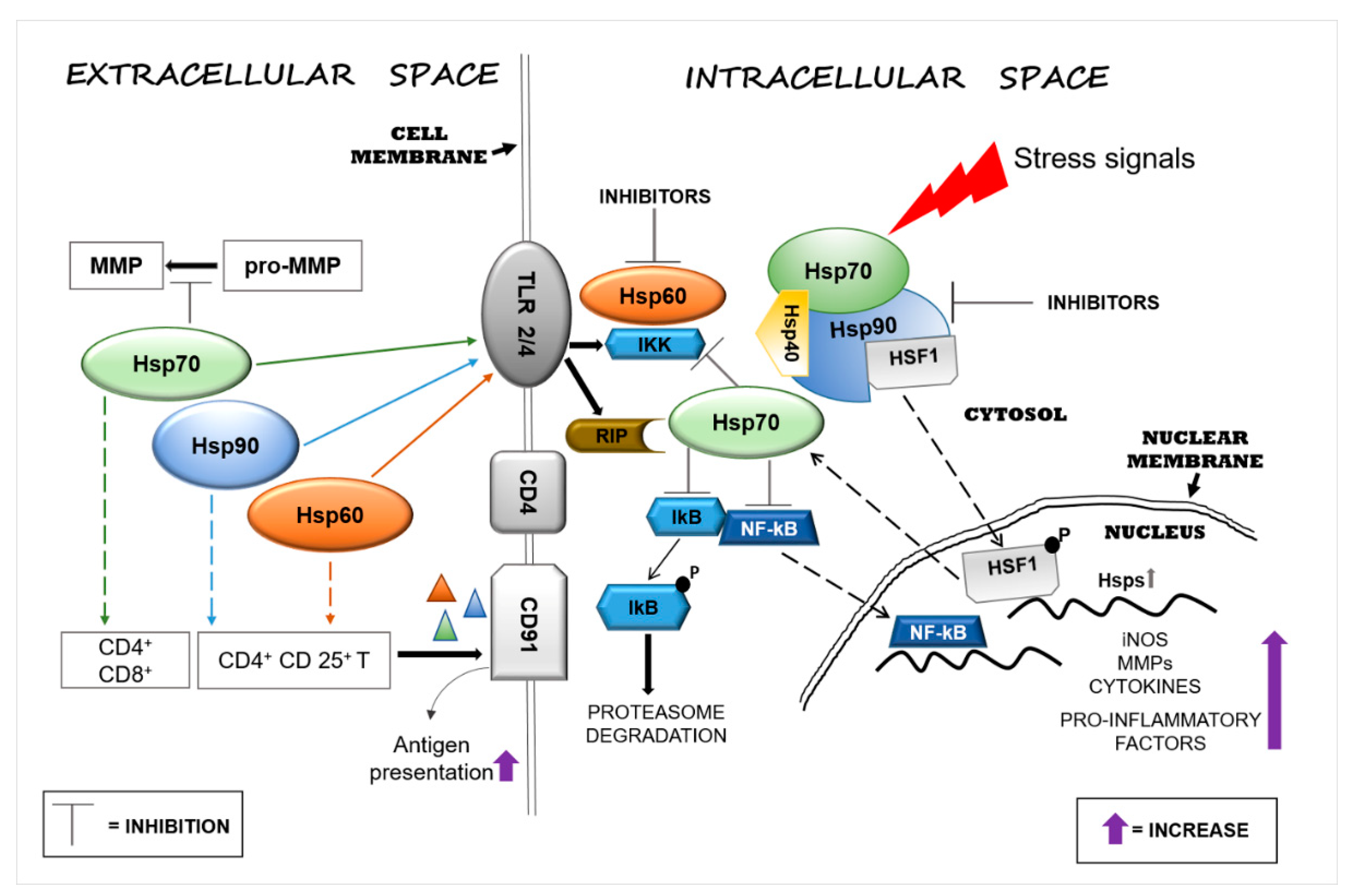
Applied Sciences Free Full Text Functions And Therapeutic Potential Of Extracellular Hsp60 Hsp70 And Hsp90 In Neuroinflammatory Disorders Html
Block Diagram of Wireless Power Transmission Project Circuit using 555 Timer IC Transmitter Receiver Components Required Note.

. A block diagram of the demonstration components is shown below. Block diagram of WPT system. Long Distance Power Transfer Technique.
Transmitter and Receiver coils are built by. The wireless networks solution extends conceptdraw diagram software with professional diagramming tools set of wireless network diagram templates and samples comprehensive. Then the transmit-ter coil.
Design and Simulation of Single Phase and Three Phase Wireless Power Transfer. The primary components include a microwave source a transmitting antenna and a receiving rectenna. Maximum power from a low voltage input supply 3V to 55V to a tuned receiver.
Maths involves in Wireless Mobile Charger Circuit Diagram The entire calculation shown below is done by considering the parts list value in this circuit. Applications of RF Transceiver. AbstractWireless power transfer WPT is an emerging technology that can realize electric power transmission over certain distances without physical contact offering significant.
Figure 13 Equivalent Circuit of the Odd Mode Wilkinsons Divider 25 Figure 14 Simple Block Diagram of Transceiver Circuit 30 Figure 15 Transmission System Employing Different. RF transceiver module is used in wireless communication. The ltc4125 enhances a basic wireless power transmitter by providing three additional key features.
An autoresonant function that maximizes available receiver power an optimum. 1 shows block diagram of the. 25 frequency modulation transmitter block diagram Rabu 21 September 2022 RECEIVER 41 Introduction 25 42 Sensitivity and Selectivity 25 4.
Download scientific diagram Block diagram of the Wireless Power Transmission from publication. A Review Transfer Psychology Transfer and. To optimize system efficiency the LTC4125 employs a periodic transmit power search and adjusts the.
Download scientific diagram Block diagram of wireless power transmission from publication. The main application of this transceiver is to make information in the form of. 222A shows the physical representation of a typical IPT systemAccording to Amperes law the current I P A flowing through a primary coil produces a magnetic field.
Block diagram of wireless power transfer system In this project supply voltage 12 DC drives oscillator circuit as push-pull driver to operate transmitter coil.
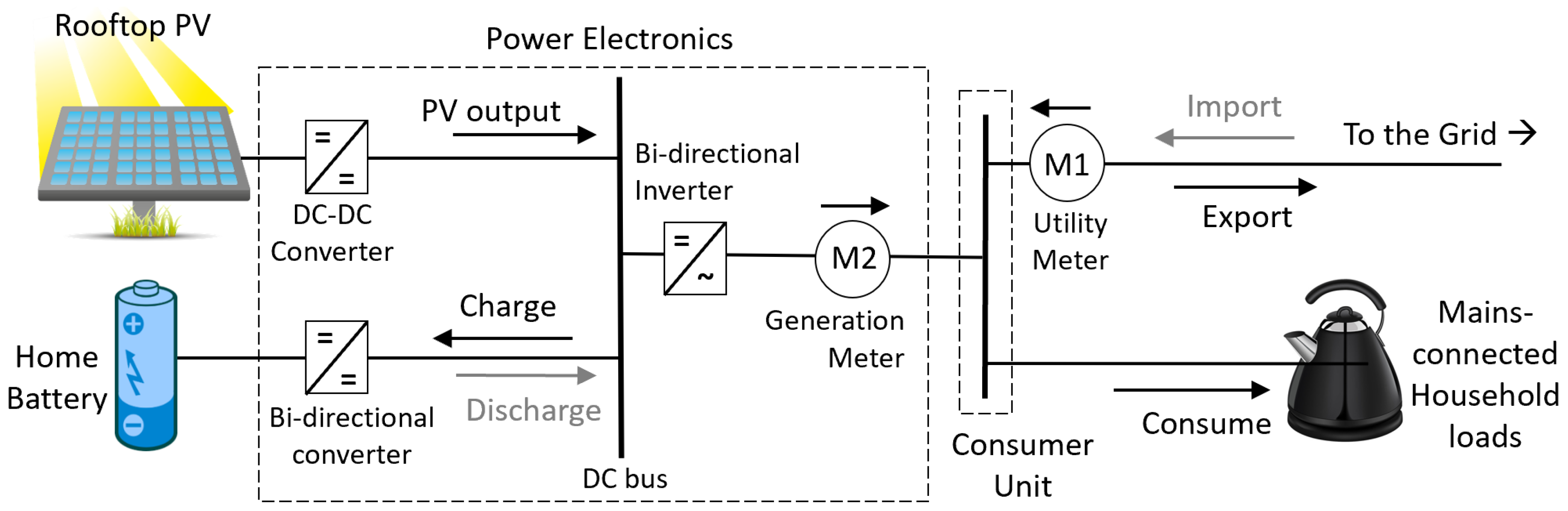
Energies Free Full Text An Emissions Arbitrage Algorithm To Improve The Environmental Performance Of Domestic Pv Battery Systems Html
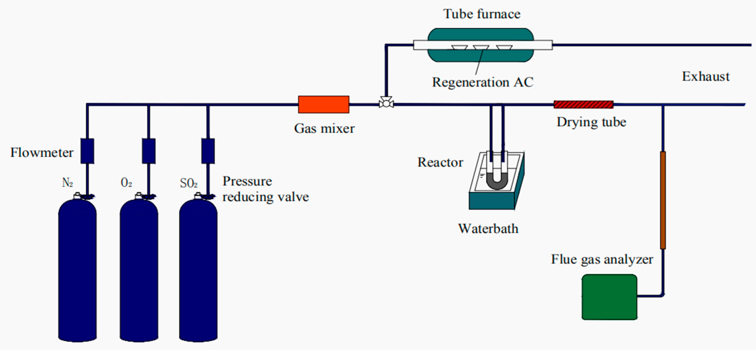
Applied Sciences Free Full Text Regeneration Performance Of Activated Carbon For Desulfurization Html
Tom Hand 39 S Guide To The Chrysler Torqueflite Automatic Transmission Transmission Automatic Transmission Block Diagram
2
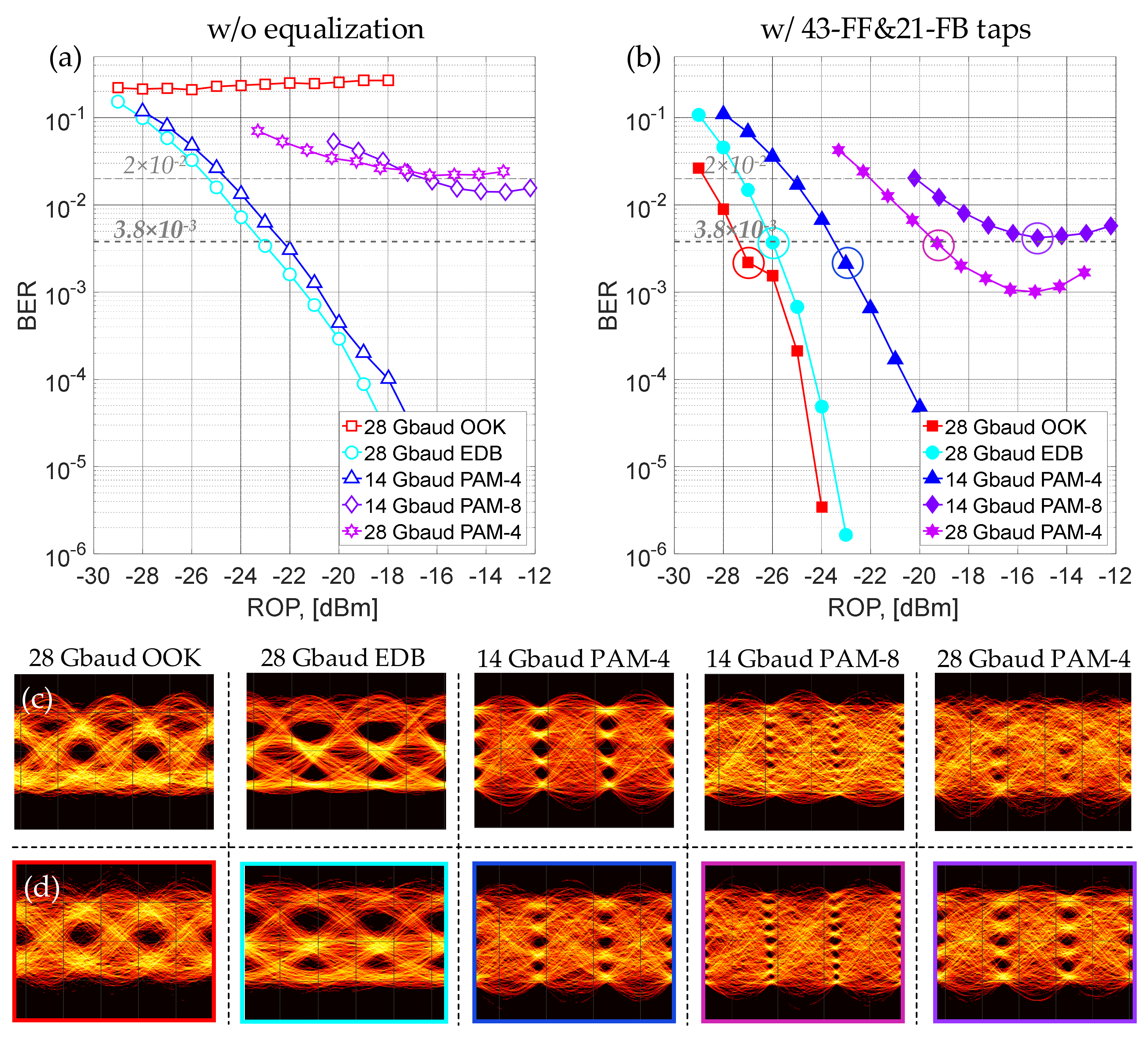
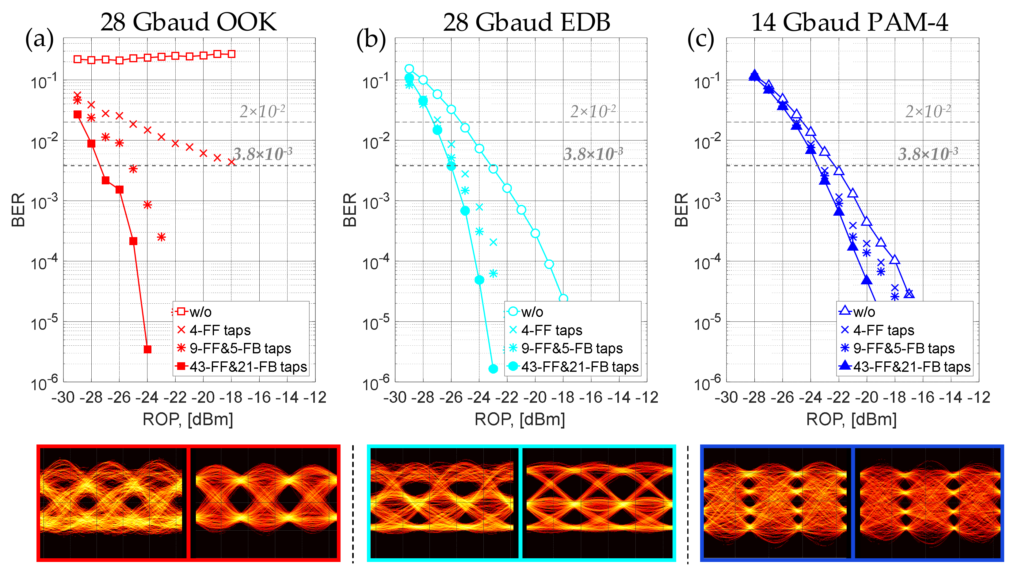
Applied Sciences Free Full Text Optical Power Budget Of 25 Gbps Im Dd Pon With Digital Signal Post Equalization Html
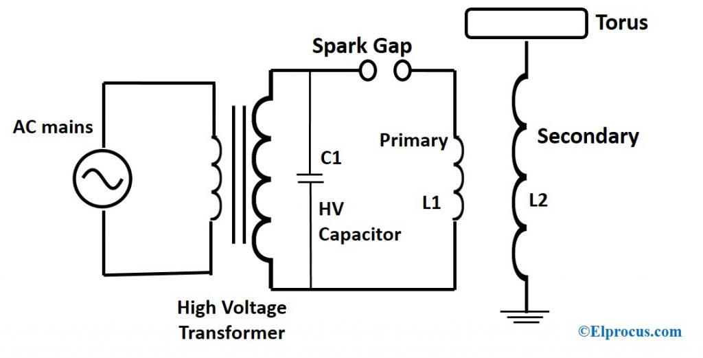
Tesla Coil Working Principle Circuit And Applications
2
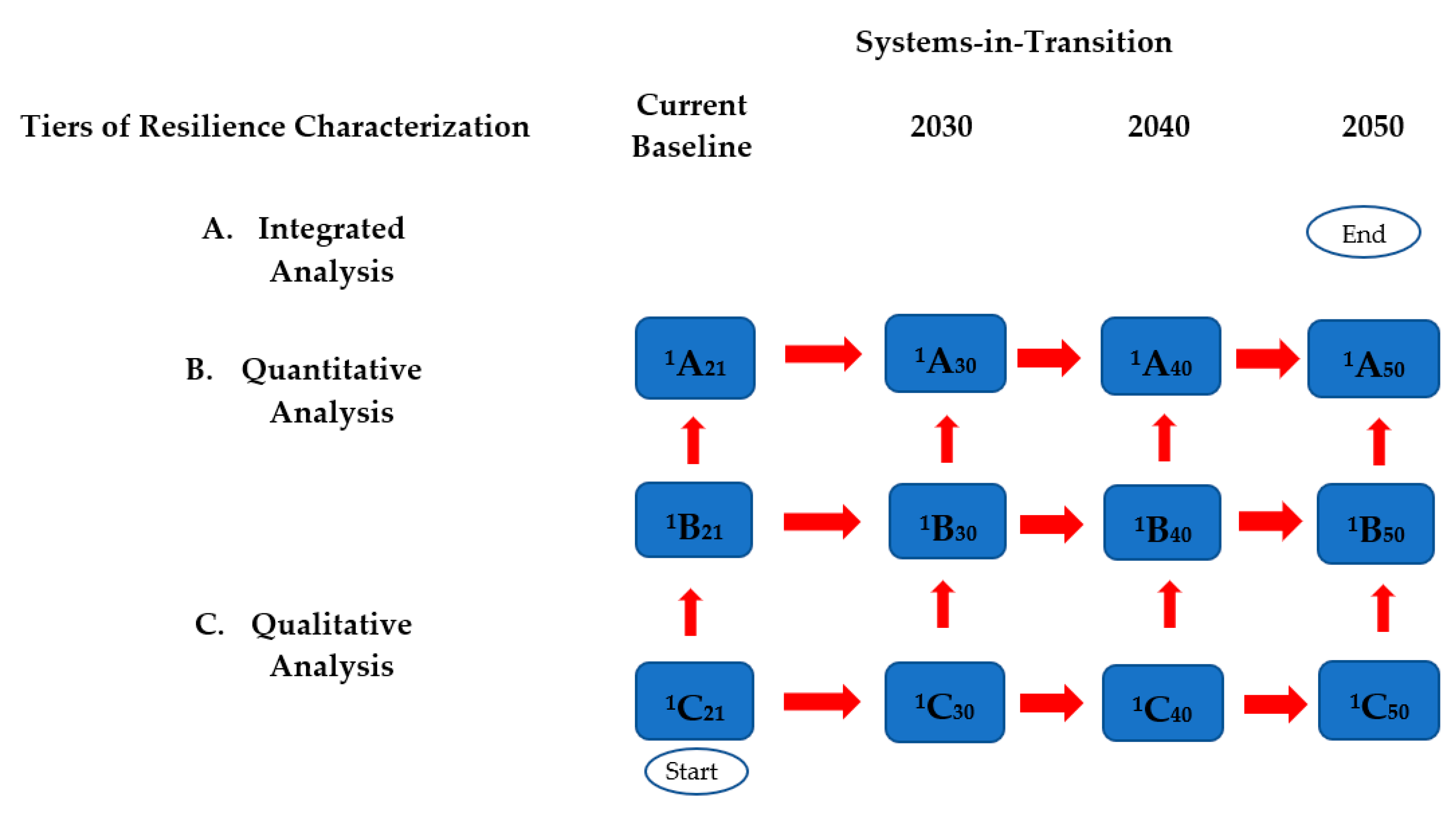
Energies Free Full Text A Meta Level Framework For Evaluating Resilience In Net Zero Carbon Power Systems With Extreme Weather Events In The United States Html
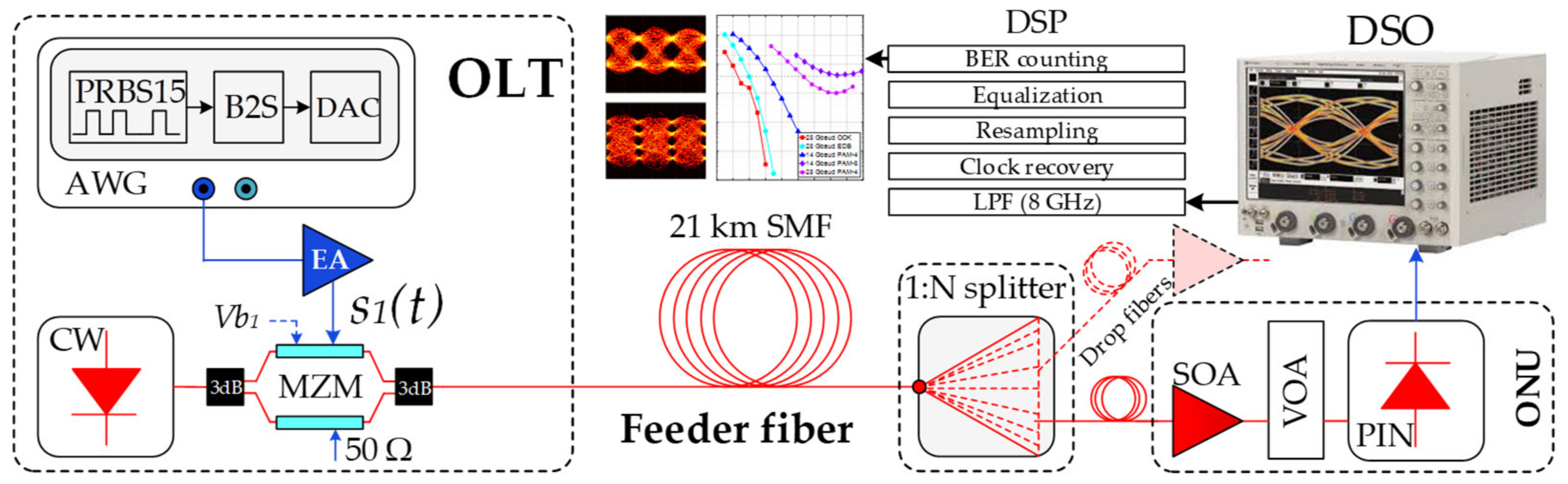
Applied Sciences Free Full Text Optical Power Budget Of 25 Gbps Im Dd Pon With Digital Signal Post Equalization Html
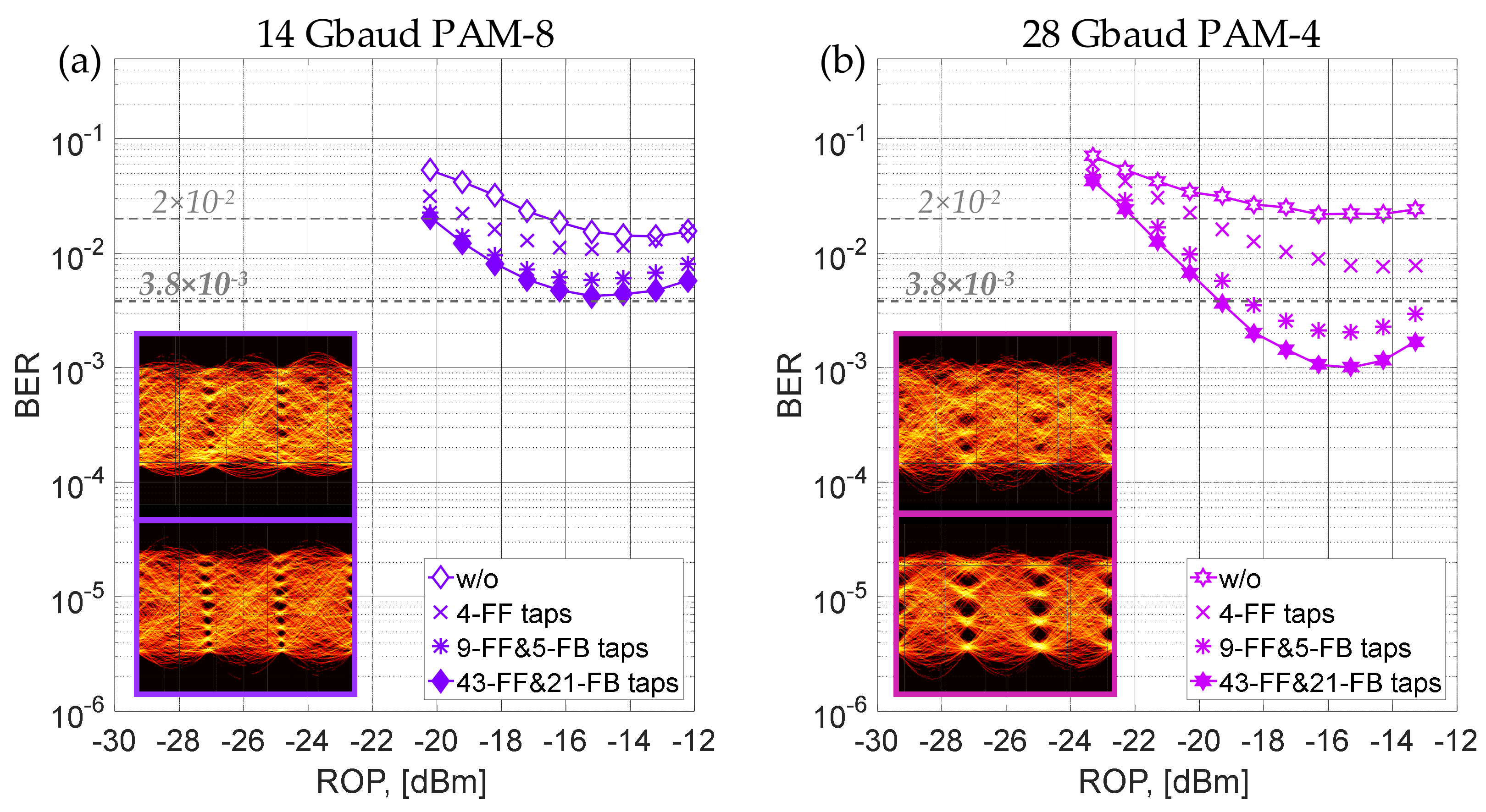
Applied Sciences Free Full Text Optical Power Budget Of 25 Gbps Im Dd Pon With Digital Signal Post Equalization Html

48 Volt Starter Generator
Applied Sciences Free Full Text Optical Power Budget Of 25 Gbps Im Dd Pon With Digital Signal Post Equalization Html
![]()
Overview Of Wireless Pc Communication System Using Transceiver

Generic Block Diagram Of A Wireless Power System Circuit Projects Wireless Power
2
Aerospace Free Full Text Heavy Ion Induced Single Event Effects Characterization On An Rf Agile Transceiver For Flexible Multi Band Radio Systems In Newspace Avionics Html

Block Diagram Of Modulated Ir Transmission And Reception Block Diagram Communication Networks Diagram